The real challenge is to get a head mapped all the way around. Cylindrical mapping helps us quite a bit, but there is still that problem with how to generate the textures. On the source code page there is a plug in for 3D Studio Max® that will help you generate a single unfolded texture. It may seem like it isn’t too difficult to do, but after this explanation you would probably agree that this was one of the most difficult pieces of code to write. What we want to accomplish is the ability to map to orthogonal view pictures into one texture map.
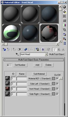
For the plug-in to work we need to set up some mapping for the head that was created. Create a Multi/Sub-Object in the material editor of 3D Studio Max®. Set the number of sub-objects to four by clicking on the set number. Next create four sub-materials that have textures. The first one should have its material ID set to 1. This one will be used for the cylindrical map that will be applied in the final stage. The plug-in used the Material IDS to figure out which side of the head the 2D texture is being applied to. The IDS are preset in the plug-in as follows:
For the pictures that were used earlier, we will planar map these pictures on the left, right (for the side view) and the front for the front view. Here is how the material editor should have been set up.
Figure 11
We must now use the UVW Mapping modifiers to map the
pictures onto the head. For mapping the
first material ID (1), just use cylindrical mapping with a dummy texture for
now. This will be explained in a little
bit. Now map the 2 photographs by adding
UVW Mapping modifiers for each of the faces. In this example, the left, right
and front were planar mapped onto the object.
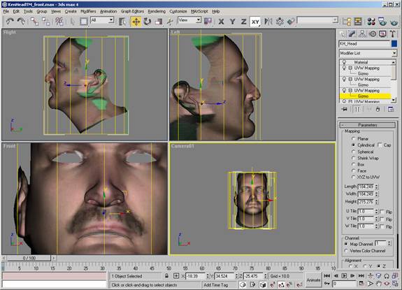
Figure 12
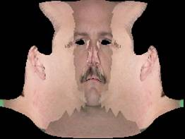
Make sure you have installed the unwrap.dlu plug-in in your 3D Studio MaxÒ “plugins” directory. We will delve into this tools source code a little later. For now select the Utilities panel (the hammer). Next select the “more..” button. Then scroll down until you find the utility named “Unwrap Object Texture” and then click “OK”. Most of the defaults are fine, except that you do want to select the “Spline Blending” radio button. The differences between no spline blending and spline blending can be seen in Figure 13. The algorithm for selecting the triangles to render is based on using the normal of the triangle and doing a dot product with the direction of the unit cube. This then selects the texture map, which is most likely to contribute the “best” pixels to the triangle. There could have been some sort of simple blending done, but there was a better solution.
Figure 13
 |
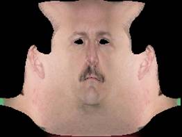 |
| Normal Based |
|
This tool was quite a feat to write and hopefully you will
really get some use out of it. Peter
Watje wrote the original program and my thanks go out to him for his fine
work. The code was since modified and
texture mapping was added. Chris Hecker
wrote the original texture mapping code, but it was modified to fit into this
framework. The last part of the code is
the actual difficult part. It was very
hard and very frustrating to write. The code is based on a paper written by
Peter J. Burt and Edward H. Adelson entitled “A Multiresolution Spline with
Application to Image Mosiacs. The difficult part of the code was
decomposing the images into Gaussian and Laplacian Image Pyramids. The code uses memory quite heavily and the
plug-in will warn you that it can take a while to generate the images and then
merge them all back together. On a
Pentium III 500 MHZ, it takes about 20 seconds.
The time to generate the map is acceptable given the results of the
blending. Save this image to the disk.
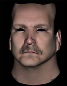
Figure 14